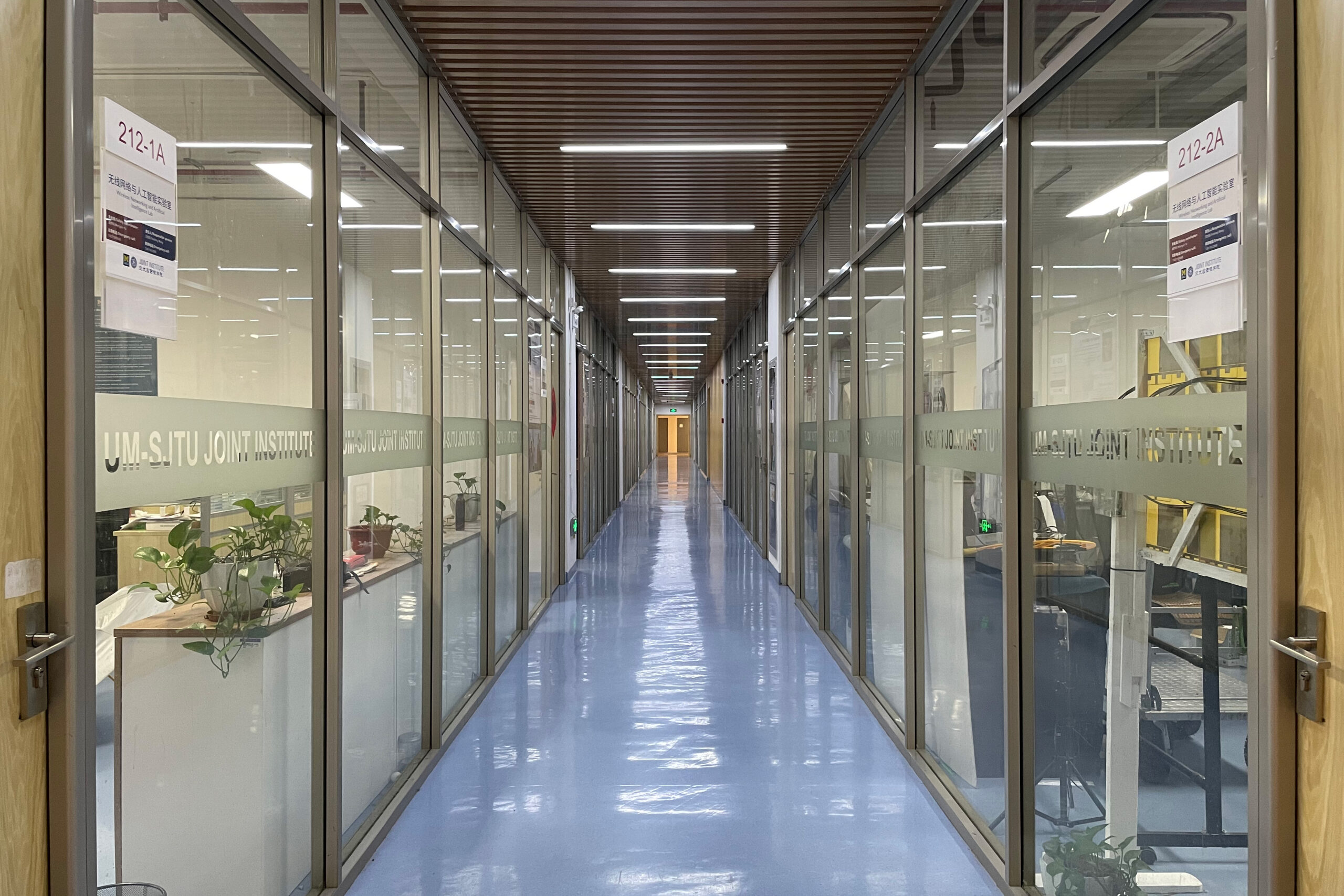
Terahertz Wireless Channel Dataset

World’s leading dataset of Terahertz wireless channels based on real-world channel sounders and simulators

15 +

Scenarios

up to 400 GHz

Measuring frequency

60 w+

CIR data

THz Channel Measurement

The wireless propagation channel is the medium over which transportation of the signals from the transmitter (Tx) to the receiver (Rx) occurs, and as a consequence, channel properties determine the ultimate performance limits of wireless communications, as well as the performance of specific transmission schemes and transceiver architectures. Since wireless channels are the foundation for designing a wireless communication system in the new spectrum and new environments, it is imperative to study the THz radio propagation channels for 6G future wireless communications. Studying wireless channel features relies on the physical channel measurements with channel sounders. The characteristics of the wireless channel are then analyzed based on the measurement results for developing channel models. Channel models capture the nature of wave propagation with reasonable complexity and allow the fair comparison of different algorithms, designs and performance in wireless networks. channel characteristics in the THz band might be different from those of the mmWave and cmWave bands. Due to the smaller wavelength, waves in the THz band interact through reflection, scattering and diffraction with smaller environmental structures, such as surface roughness with sub-millimeter dimensions, and suffer from absorption and scattering by molecules and tiny particles in the atmosphere. They therefore exhibit unique behaviors compared with those in lower frequency bands. Though methodologies of channel modeling in the THz band inherit from those in the mmWave band, a specific modeling and parameterization of THz channels is still required in order to accurately characterize THz wave propagation for diverse application scenarios for 6G.

Measurement Scenario and Results

1. Corridor​

The corridor is on the second floor of the Longbin Building in Shanghai Jiao Tong University. Both sides of the corridor are furnished with glass walls. To connect pieces of glass together, metal pillars are installed on the glass walls. The separation distance between the consecutive metal pillars is around 1.26 m. Laboratory rooms lie on both sides of the corridor, furnished with wooden doors with width around 0.93 m. Moreover, an around 7 m-long segment of the walls on the southern side is covered with wood. Besides, the concrete walls are on both ends of the corridor.​
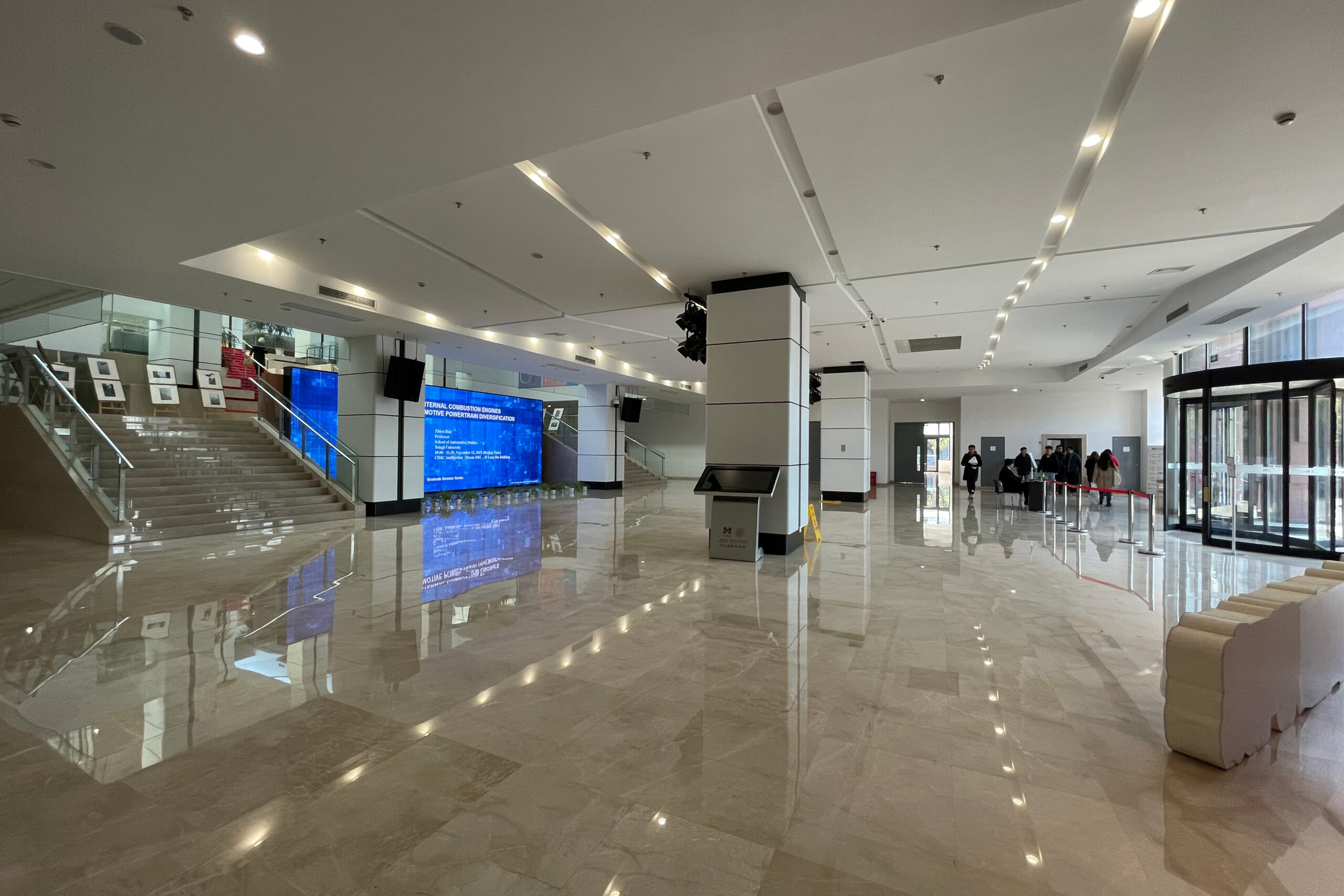
Frequency306-321 GHz
# PositionLoS*21, NLoS*3
# CIR24*36*5
Distance5.1-31.2 m
Tx height2.5 m
Rx height2 m

Y. Li, Y. Wang, Y. Chen, Z. Yu, and C. Han, “Channel Measurement and Analysis in an Indoor Corridor Scenario at 300 GHz,” in Proc. of IEEE International Conference on Communications (ICC), pp. 1–6, Jun. 2022.

2. Lobby​

The measurement campaign is conducted in the lobby on the ground floor of the Longbin building on the SJTU campus. The major area is the rectangular environment in front of the stairs with more than 500 m2, including a glass revolving gate on the north, four symmetrically distributed pillars in the middle, and one LED screen on the south. Two narrow corridors are extended to the west and east, respectively.
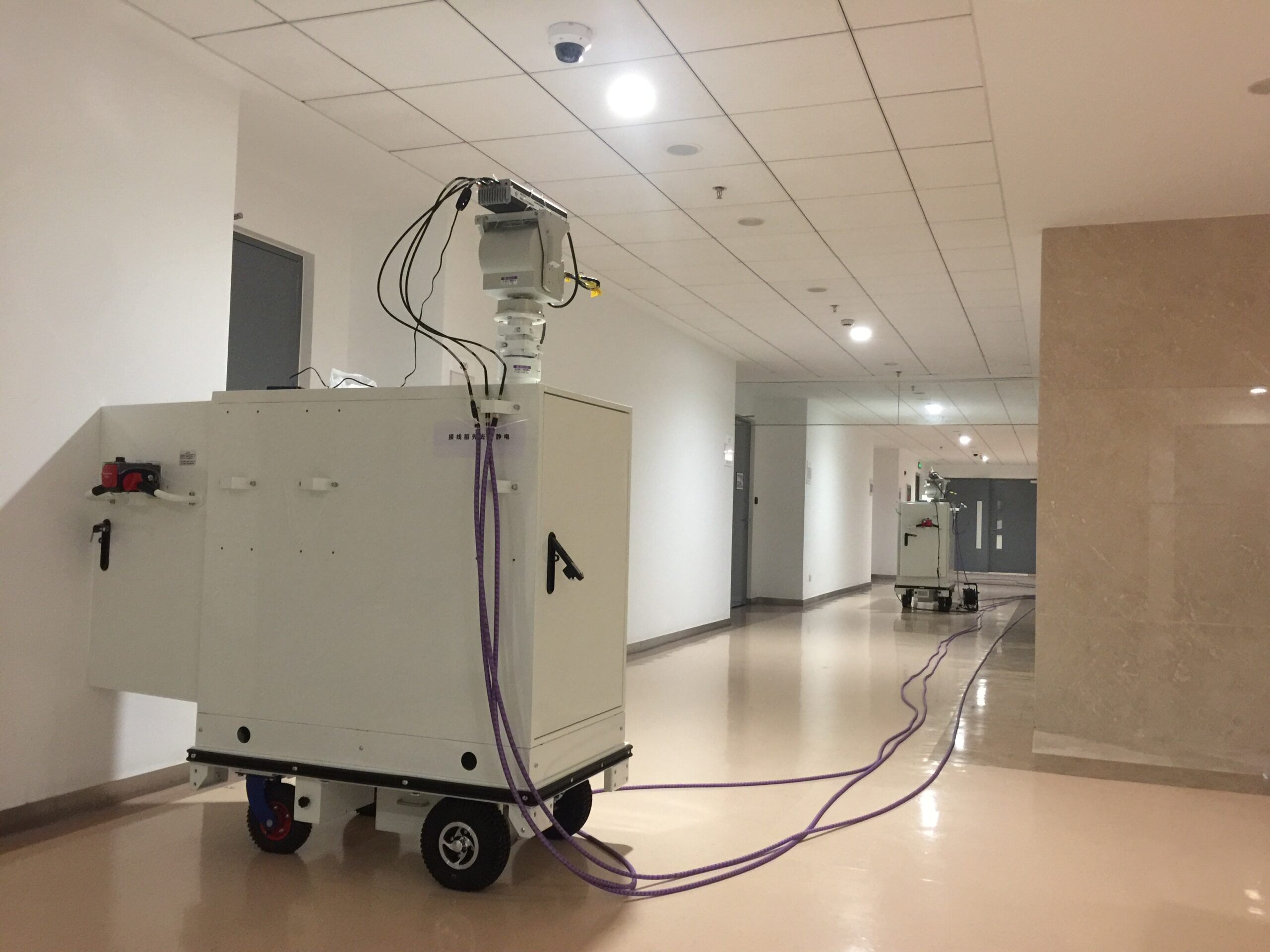
Frequency306-321 GHz
# PositionLoS*18, NLoS*3
# CIR21*36*5
Distance7.1-18.9 m
Tx height2.5 m
Rx height2 m

Y. Wang, Y. Li, Y. Chen, Z. Yu, and C. Han, “300 GHz Wideband Channel Measurement and Analysis in a Lobby”, in Proc. of IEEE International Symposium on Personal, Indoor and Mobile Radio Communications (PIMRC), Toronto, Canada, Sept. 2023.

3. L-shaped hallway ​

The hallway is on the second floor of the Longbin Building in Shanghai Jiao Tong University. The scenario mainly consists of two perpendicular corridors, connected by a corner. The long corridor is 2.97 m wide and 32.53 m long, including two 3 m long extensions at both ends. Indented offices are distributed along the corridor, whose depth is about 0.6 m with doors closed. The other corridor is 7 m wide which extends all the way to the left end.
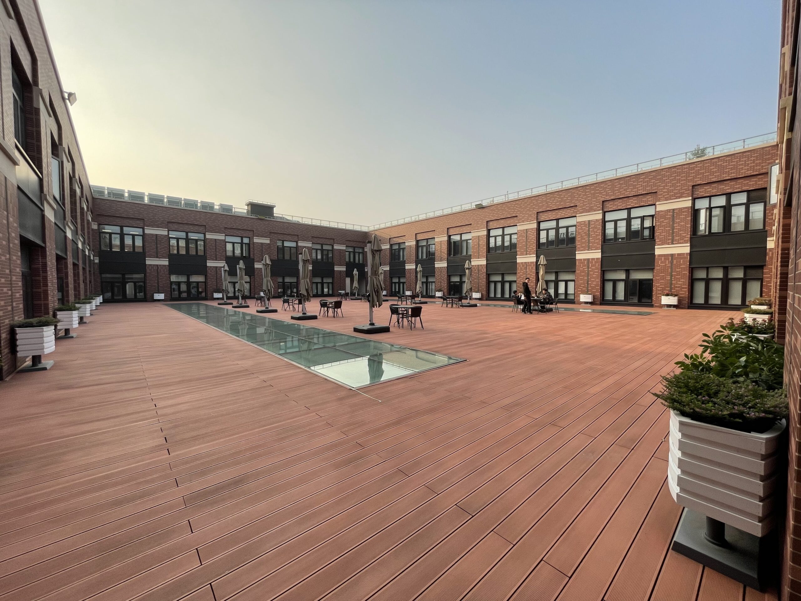
Frequency306-321, 356-371 GHz
# PositionLoS*4, NLoS*14
# CIR2*18*36*5
Distance7.7-23.8 m
Tx height2 m
Rx height1.75 m

Y. Wang, Y. Li, Y. Chen, Z. Yu, and C. Han, “0.3 THz Channel Measurement and Analysis in an L-shaped Indoor Hallway,” in Proc. of IEEE International Conference on Communications (ICC), pp. 1–6, Jun. 2022.

4. Atrium

The outdoor atrium is on the fourth floor of the Longbin Building in Shanghai Jiao Tong University. In the center area of the atrium, there are many glass desks and metal pillars. Moreover, around the atrium, there are four concrete walls, furnished with glass windows and metal window frames. For the floor of the atrium, it is mostly made with wood, except two small areas furnished with glass. Furthermore, The length and width of the atrium are 34.4 m and 25.6 m, respectively.
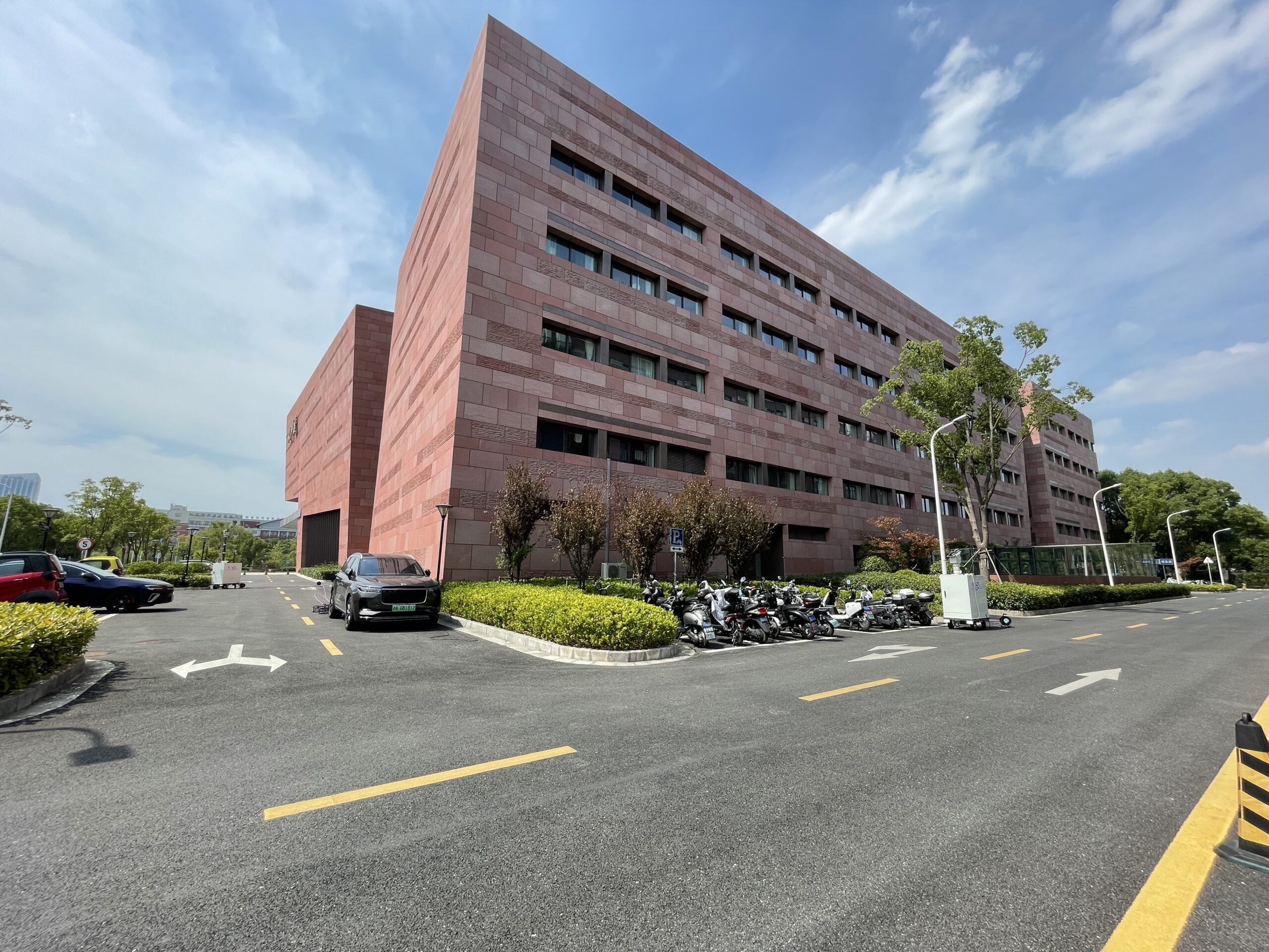
Frequency306-321 GHz
# PositionLoS*21
# CIR21*36*5
Distance7.0-18.3 m
Tx height2.2 m
Rx height1.5 m

Y. Li, Y. Wang, Y. Chen, Z. Yu, and C. Han, “300 GHz Channel Measurement and Characterization in the Atrium of a Building”, in Proc. of European Conference of Antennas and Propagation (EuCAP), pp.1-6, 2023.

5. Street

The measurement campaign is conducted in the outdoor street bounded by Wenbo Building, Longbin Building, and Nanyang Road on the SJTU campus. Specifically, we focus on the L-shaped turning at the crossroad, depicted as the yellow region, with buildings, vehicles, pedestrians, plants, etc. The west street (Street A) is between the west wall of Wenbo Building and a parking area. Vehicles, lamp poles and traffic signs are found along Street A, and one lamp pole is at the southwest corner of Wenbo Building. The other street canyon (Street B) between two buildings is about 22.32 m wide. Plants and a non-automobile parking area are located in the south of Wenbo Building along Street B.
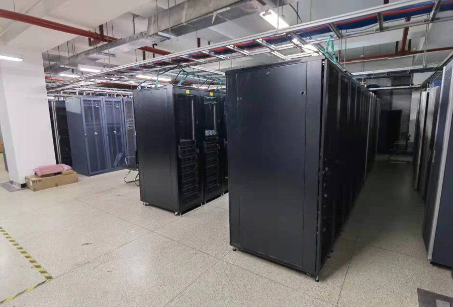
Frequency306-321, 356-371 GHz
# PositionLoS*8, NLoS*10
# CIR2*18*36*5
Distance10.3-38.3 m
Tx height3 m
Rx height1.75 m

Y. Wang, Y. Li, Y. Chen, Z. Yu, and C. Han, “Terahertz-Band Channel Measurement, Analysis and Modeling for an L-shaped Hallway,” in Proc. of IEEE International Conference on Communications (ICC),pp. 1–6, May. 2023.

6. Data center

The measurement campaign locates in a data center on the second floor of 3G Building in China Academy of Information and Communications Technology (CAICT). Plenty of rack servers are placed in the data center, which are divided into ten columns of racks with around 1 m aisles between two columns. Besides, there is a 2.5 m wide corridor in the north direction of all the racks, where two concrete pillars are built.
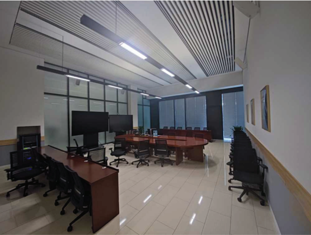
Frequency130-140 GHz
# PositionLoS*14, NLoS*12
# CIR18*36*5+8*36*4
Distance1.5-7.9 m
Tx height2 m
Rx height1.6 / 2.0 m

G. Song, Y. Li, J. Jiang, C. Han, Z. Yu, Y. Du, and Z. Wang, “Channel Measurement and Characterization at 140 GHz in a Wireless Data Center”, in Proc. of IEEE Global Communications Conference (GLOBECOM), pp.1-6, 2022.

7. Meeting room

The meeting room has an area of 10.15 m × 7.9 m and the ceiling height of 5.8 m. In the meeting room, a 4.8 m × 1.9 m desk with a height of 0.77 m is placed in the center, while eight chairs are around the desk. In addition, two televisions are closely placed in front of the north wall. The material of east wall is glass, while the other three are made of lime.

Frequency130-143, ~200 GHz
# PositionLoS*12/10
# CIR(12+10)*36*5
Distance1.4-8 m
Tx height2 m
Rx height1.4 m

Z. Yu, Y. Chen, G. Wang, W. Gao and C. Han, “Wideband Channel Measurements and Temporal-Spatial Analysis for Terahertz Indoor Communications,” in Proc. of IEEE International Conference on Communications Workshops (ICC Workshops), pp. 1-6, 2020.

Y. Chen, Y. Li, C. Han, Z. Yu and G. Wang, “Channel Measurement and Ray-Tracing-Statistical Hybrid Modeling for Low-Terahertz Indoor Communications,” IEEE Transactions on Wireless Communications, vol. 20, no. 12, pp. 8163-8176, Dec. 2021.

J. He, Y. Chen, Y. Wang, Z. Yu and C. Han, “Channel Measurement and Path-Loss Characterization for Low-Terahertz Indoor Scenarios,” in Proc. of IEEE International Conference on Communications Workshops (ICC Workshops), pp. 1-6, June 2021.

8. Office room

The dimensions of the office room in our channel measurement campaign are 30 m × 20 m, including a hallway and an office area. In the north of the office room, there is a 30-meter-long hallway. In the office area, the space is partitioned by plastic boards into individual personal zones. On each desk, there are two monitors as well as other work-related items.
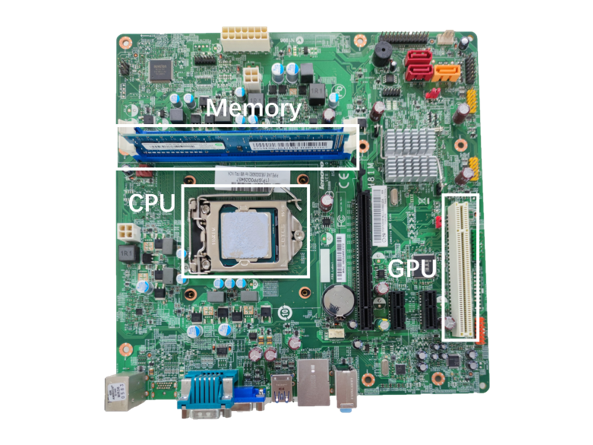
Frequency130-143, ~200 GHz
# PositionLoS*54, NLoS*20
# CIR2*74*36*5
Distance2-30 m
Tx height 
Rx height 

J. He, Y. Chen, Y. Wang, Z. Yu and C. Han, “Channel Measurement and Path-Loss Characterization for Low-Terahertz Indoor Scenarios,” in Proc. of IEEE International Conference on Communications Workshops (ICC Workshops), pp. 1-6, June 2021.

Y. Chen, C. Han, Z. Yu and G. Wang, “140 GHz Channel Measurement and Characterization in an Office Room,” in Proc. of IEEE International Conference on Communications (ICC), pp. 1-6, June 2021.

9. Motherboard

The THz measurement campaign is conducted on a computer motherboard. There are many components on the motherboard, mainly including center processing unit (CPU), graphical processing unit (GPU), memory chips, among others. Three measurement cases are investigated, namely the LoS, NLoS and RNLoS cases, which are introduced in detail as follows.

Frequency100-140 GHz
# PositionLoS*12, NLoS*42
# CIR54*2001
Distance0.16-0.3 m
Tx height0.02 m
Rx height0.02 m

Y. Li, G. Wang, G. Song, M. Xu, J. Jiang, and C. Han, “Wideband Channel Measurement and Characterization on a Computer Motherboard”, in Proc. of IEEE Global Communications Conference Workshop(GLOBECOM Workshop), pp.1-6, 2022.


Measurement System

The channel measurement platform supports the frequency ranging from 260 GHz to 400 GHz. The system is composed of the Tx module, the Rx module, and the Ceyear 3672C VNA. The VNA generates radio frequency (RF) and local oscillator (LO) sources. The signals from RF and LO sources are multiplied by 27 and 24, respectively. As a result, the transmitted signal reaches the carrier frequencies ranging from 260 GHz to 400 GHz, and the mixed intermediate frequency (IF) signal has the frequency of 7.6 MHz. The IF signals at Tx and Rx modules are both sent back to the VNA, and the transfer function of the channel is calculated as the ratio of the two frequency responses.

*  We appreciate the collaboration with Ceyear, Nanjing Nuo Zhi Jie and National Instruments to establish our channel measurement system.

Channel Data Processing​

Data post-processing software is developed based on MATLAB. It supports quick visualization of measurement results in graphic and tabular forms, such as the power-delay-angular profiles (PDAP), clustering results, as well as channel characteristics like path loss, delay spread, and so on.​

Patent-  “基于3GPP模型的频域信道测量数据处理软件”,计算机软件发明专利2023SR0176511,2019年12月

Thanks for viewing!
Welcome to contact us: